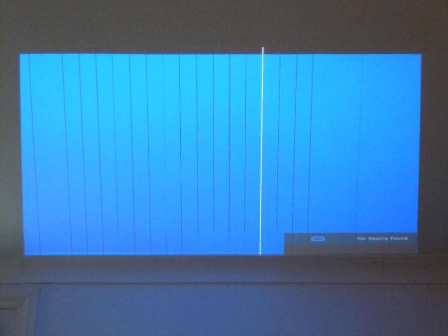
Optoma projector DS325 disassembly (Tear down) and repairCommon issuesVertical black / white lines (clean contacts)Black / white specks (replace DMD [Digital Mirror Device]) Dull / monochrome image (dust on colour wheel) Power-off after a few mins (fan not working) No power at all, plug fuse is fine (power supply board issue)
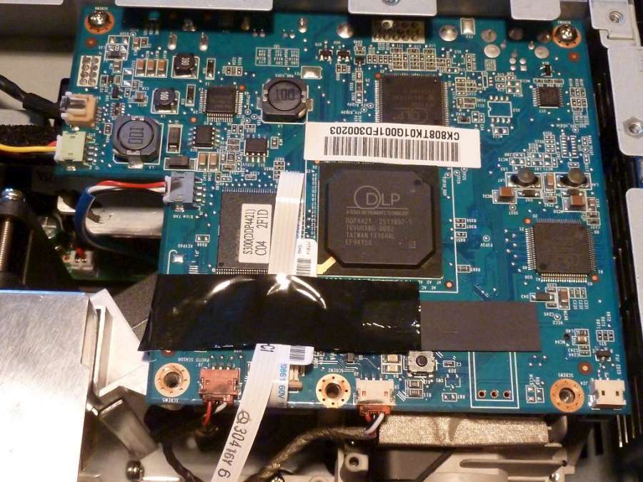
Getting insideRemove the 2 screws underneath the unit and the 2 at the back of the unit. Using an old banking card lever the top off gradually. Remove the ribbon cables connected to the main logic boardThere are 6 in total. Take care with the filament ribbon cable when removing the tape.
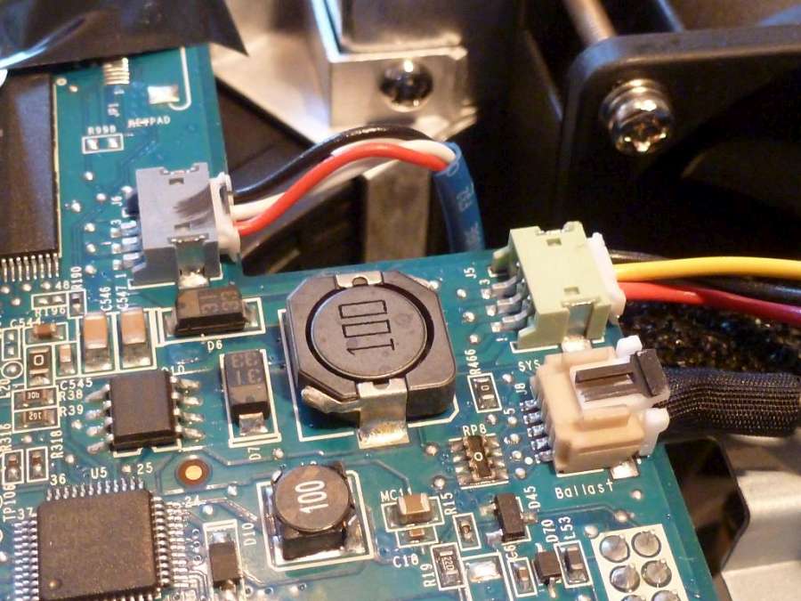
The 2 cables at the front are very similar - label one of the cables
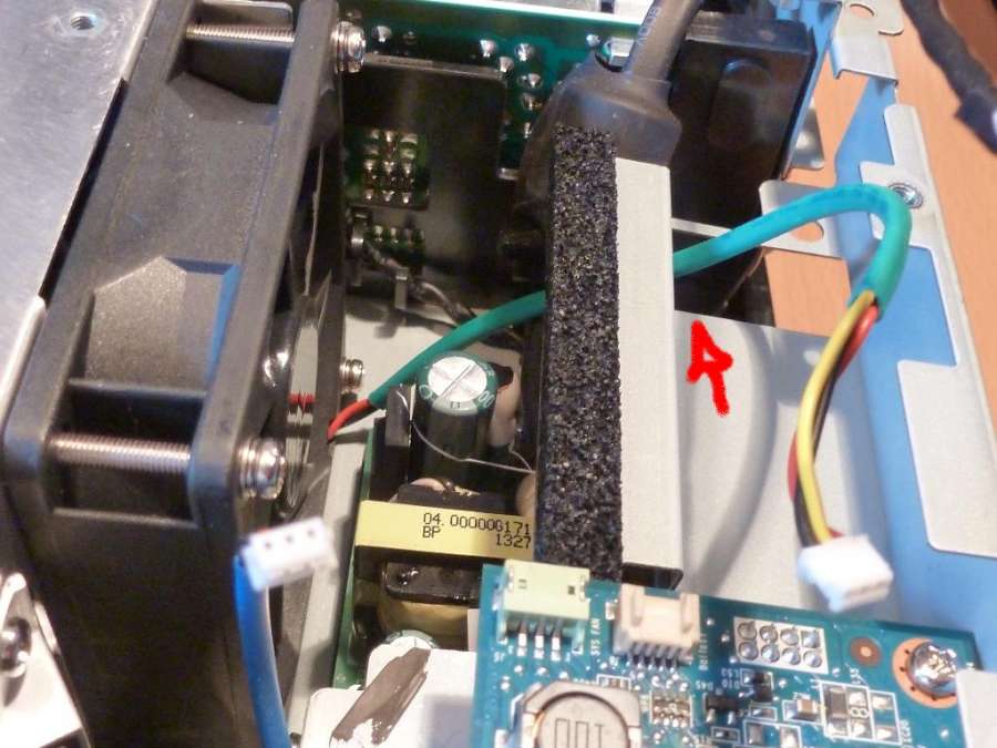
Note the routing of the green cable to the fan
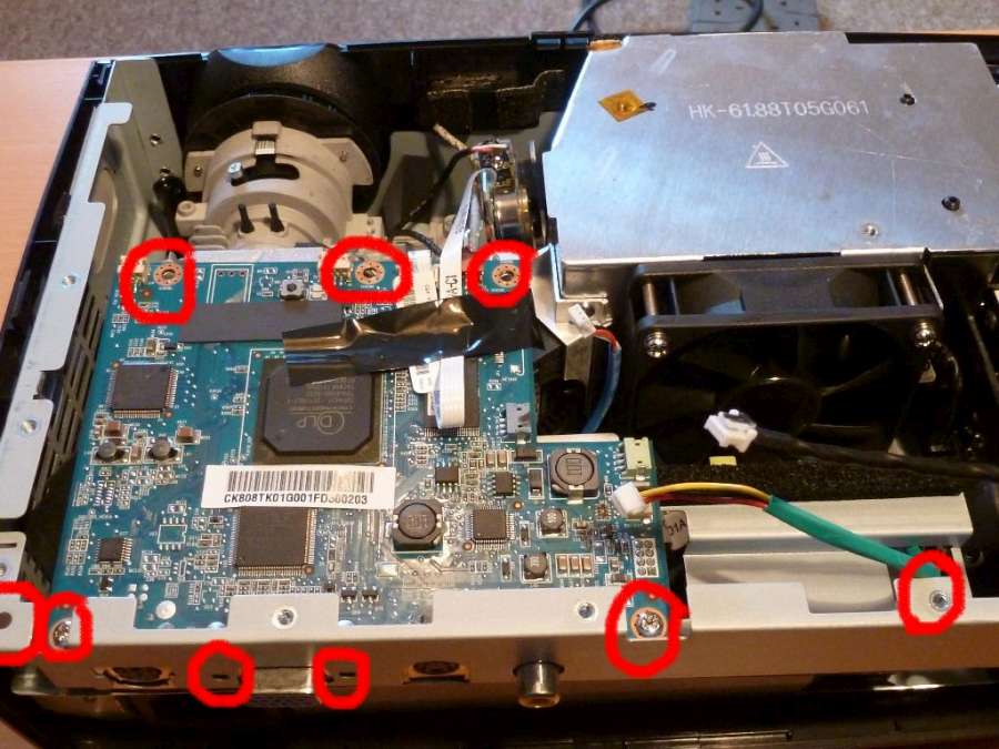
Remove the main logic boardThere are 7 internal screws and 2 external bolts that need to be removed.
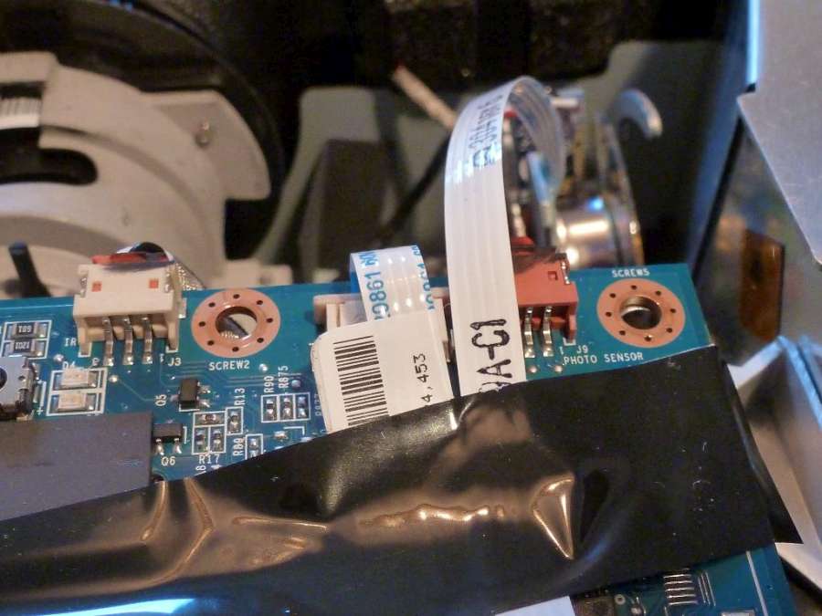
5 screws on the PCB Remove the plastic back-plate, the logic-board and the logic-board support rail. There is a connector underneath the board that should be released carefully. Examine the board very carefully using a magnifying glass for dry joints and carefully resolder obvious dry joint issues if required
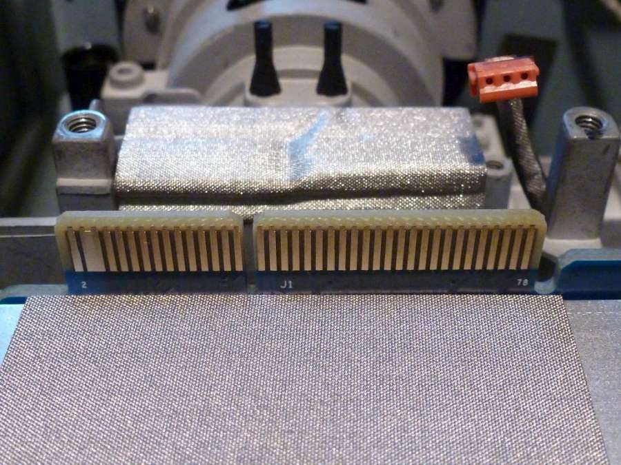
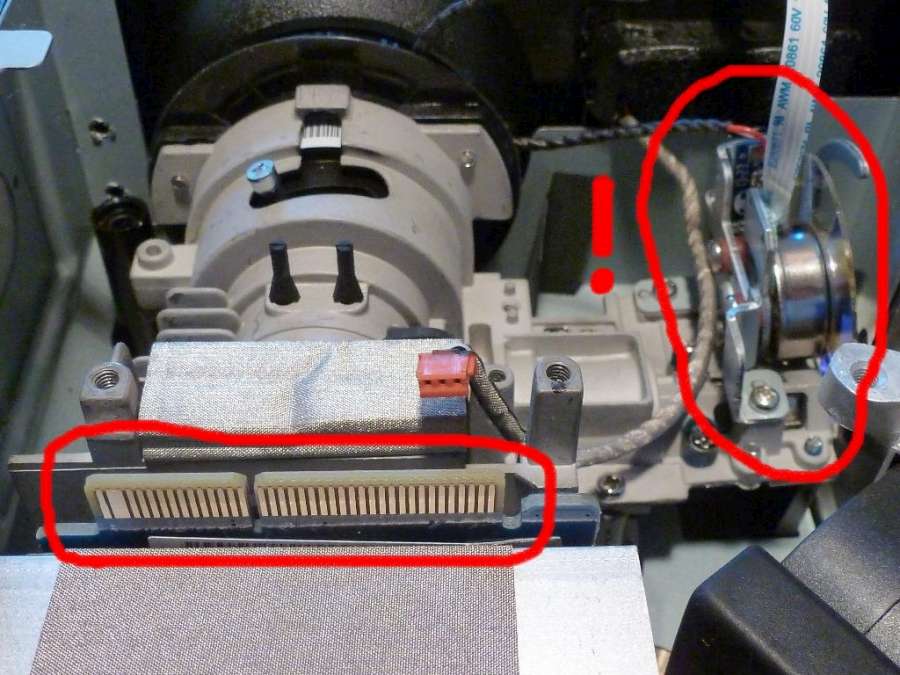
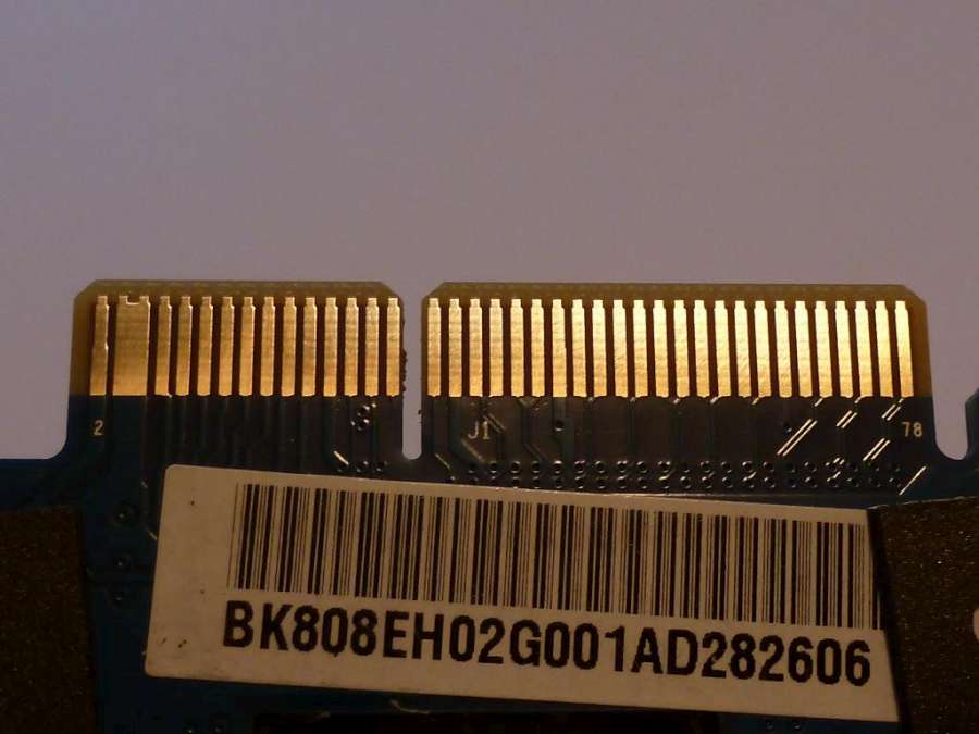
Clean the logic board / DMD board PCB connector (J1)This may be oxidised and should be cleaned using electronic contact solvents and physical abrasion.
Take care not to damage the colour wheel (to the right of the picture below)
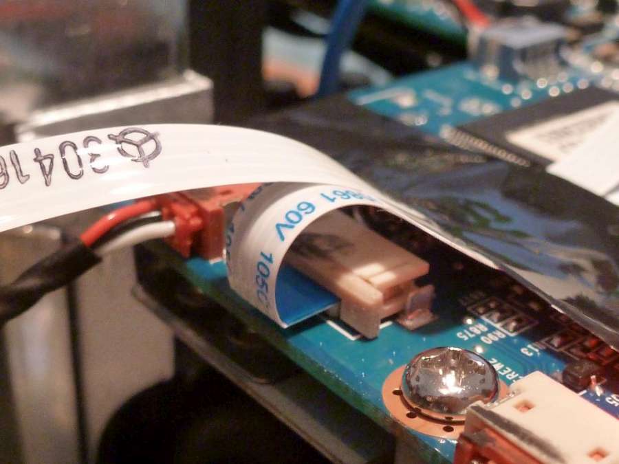
The socket under the logic board should be cleaned using solvents as far as possible
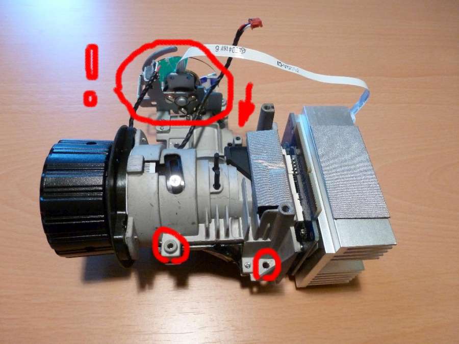
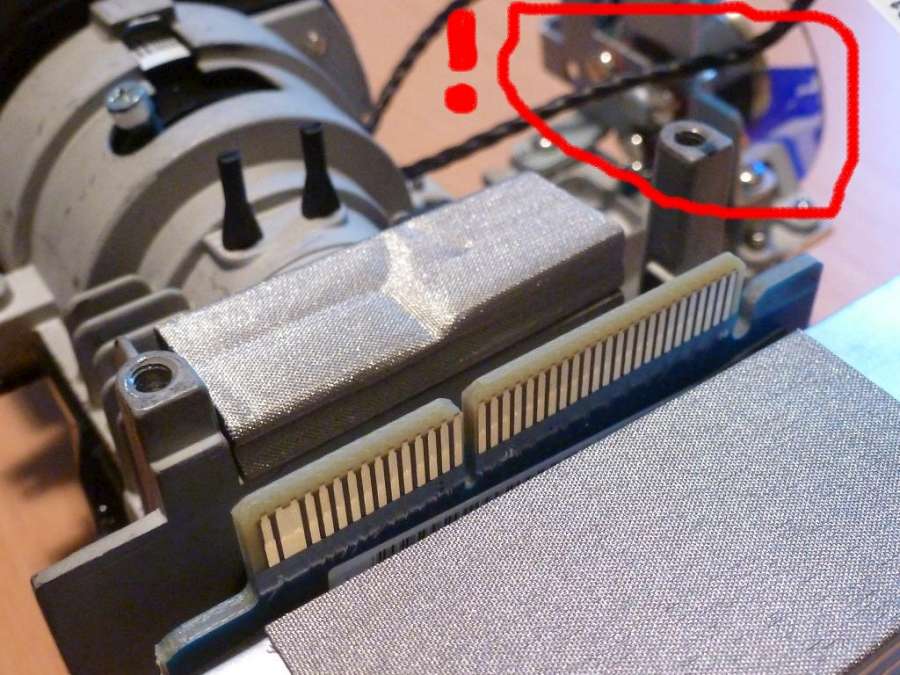
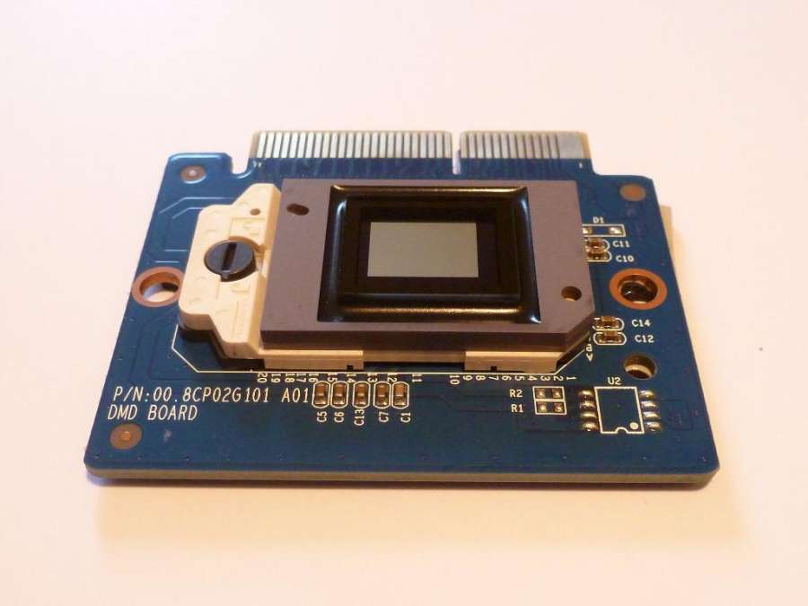
Remove the DMD board and assemblyRemove the front plastic plate (there is 1 small, silver screw inside the unit) Remove the DMD board assembly taking great care not to damage the delicate colour wheel If the colour wheel needs to be cleaned do so very carefully
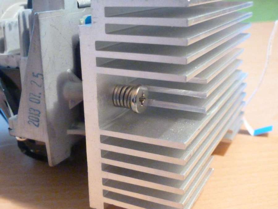
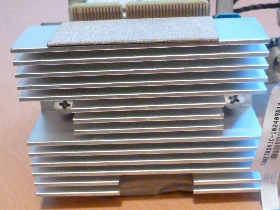
Remove the DMD heatsinkThere are 2 tensioned screws. Take care not to lose the screws or the springs. DO NOT DAMAGE THE COLOUR WHEEL.
Remove the DMD board in a dust free placeCarefully remove the DMD board taking care not to damage the black rubber gasket or the gray heat-sink pad Release the DMD chip by turning the release screw gently Inspect the chip. Is it a perfect mirror? If not, replace. Clean the chip's socket with solvent and allow time for the holes to dry
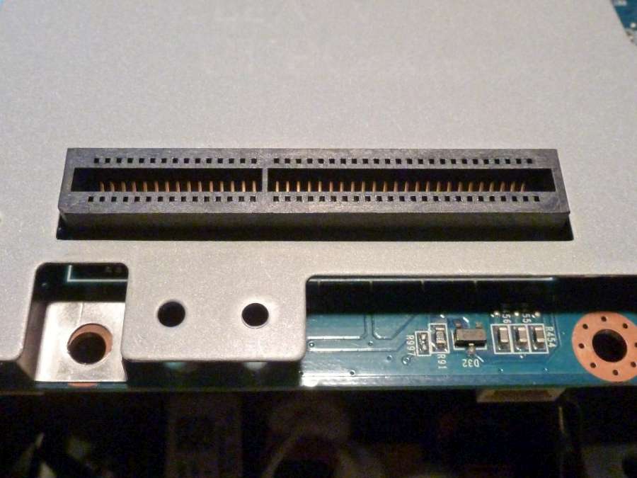
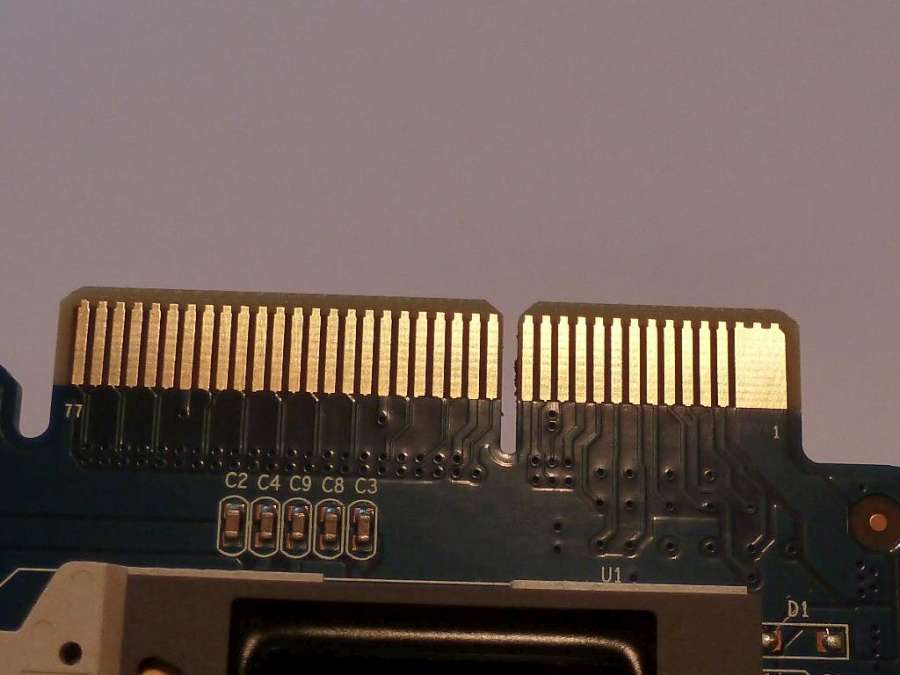
Further clean the DMD / logic board connectors (cleaned in the image below)
Reassemble carefully - ensure that the DMD is locked. Make sure that connectors are replaced correctly and that the zoom lever is in the right position. The above procedure will fix about 50% of cases where an image is being displayed
Home
|
Shop
|
Contact us
|
Therapists Toolkit
|
EMDR Software
|
EMDR Lite Software
|
Phobia Treatment Software
|
Aversion Software
|
TFT Software
|
Flooding Desensitisation / Implosion Therapy Software
|
Emetophobia Desensitization Multimedia Software
|
Desensitisation Therapy Multimedia
|
NLP Swish technique mood / state change software
|
Bilateral Audio Software
|
Drug / alcohol / food (cake / chocolate) aversion software
|
CBT / CBH Tasking Software
|
Directory / Resources |
Sitemap
EMDR, Hypnotherapy and Hypnosis in High Wycombe and Central London |
() |
Psychotherapy, hypnotherapy and hypnosis in High Wycombe
Last Updated 25 April 2024 © www.neuroinnovations.com 1998-2023
|